|
Pinhole exploration of a buried high pressure fluid-fill curved pipe. |
||
|
Introduction Previously, a pinhole exploration of a straight long pipe was made by using a linear sensor array mounted inside the pipe1),2). In the beam-forming process, the incident acoustic wave from the pipe-axis was found to estimate well the pinhole position. In this case, noise from the soil covering the pipe is of course received, but major acoustic wave propagates through the fluid of pipe where acoustic impedance at both positions of pinhole and array are equal. How about the case of the curved pipe where acoustic impedance of fluid and soil are nearly equal? In this research, pinhole exploration inside a curved pipe will be examined by simulation. Here, some assumptions were made in the simulation as follows. 1)acoustic impedance of the soil which cover the pipe is nearly equal to the fluid inside it, but other elastic wave of the soil are considered strictly. This case is regarded as "saturated soil". 2) Apart from the case of straight pipe, acoustic wave field of curved pipe can never be obtained strictly. Because an analytical wave function which corresponds to the curved coordinate system is not existed. So here, an analytical approximation method named as "Multiple Multipole Expansions" (MME) will be applied3). By the way, previously "Multiple Multipole Expansions" were applied to the simulation of cavity exploration in the quasi-homogeneous ground4). In that case, in three dimensions, wave field of reflection from the cavity was calculated so correctly, that the received data of the crossed sensor array on the ground was found to estimate the cavity position and approximate shape well.
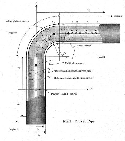
Simulations by using MME The configuration of a curved pipe where both pinhole and sensor array are mounted is shown in Fig.1.
|
||
|
Z
|
||
|
|
||
The frequency point fi used for image reconstruction were selected as fmax×0.99j−1,where fmax is upper frequency and j=1,2,..,J, but J implies the number of total sampling points. The pipe is constitutedof steel whose inside is filled with water and outside is covered with infinite soil. Inside radius of the pipe is 0.4m and thickness is 7mm. Simulation parameters are shown in Table.1.
|
||
|
|
||
|
|
||
|
|
||
|
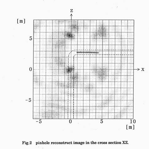
From this result, most dark point appears nearly at the origin where pinhole is located. On the other hand, similar dark point also appears at (x,z)=(0, 5.5)[m]. This reason is that beam-forming directivity of the line array has conical shape around the array axis. In general, virtual dark point like this is discarded by mounting another line array. Because, same dark point each array indicates determines exact point. However, this time, increasing both bandwidth and frequency points enables pinhole reconstruction correct. Apart from propagation only through the fluid in the straight pipe, elastic wave induced in the soil might affect to the acoustic wave received by the sensor array , but favorable result was obtained to estimate pinhole position well.
|
||
|
Conclusions Pinhole exploration inside a curved pipe was examined by simulation. Acoustic impedance of the soil which covers the pipe was assumed nearly equal to the fluid inside it, but other elastic wave of the soil was considered strictly. This case is regarded as "saturated soil". From the results, the received data of the sensor array through the soil outside the pipe was found to estimate pinhole position well.
|
||
|
References 1)Topics5, "Pinhole exploration of a buried high pressure fluid-fill pipe, 1 st study", '01.9.22 2) Topics6, "Pinhole exploration of a buried high pressure fluid-fill pipe, 2 nd study", '01.12.27 3)M.G.Imhof, " Multiple multipole expansions for acoustic scattering," J.Acoust.Soc.Am97(2),p754-763(1995) 4)Topics17, "Development of a buried object explorationsystem by crossed sensor array",'04.4.29
|
||
|
|