|
Analysis of sound field generated by a low frequency sound source in a water tank surrounded by infinite ground |
||||||||||||||||||||||||||||||||||||||||||||||||
|
1.Introduction Recently, the needs of low frequency sound source to be applied for oceanography observation or sea bottom exploration are increasing. To recognize the large structure like the ocean or earth, low frequency sound source is regarded as useful one. The reason is that the wave emanated by that has least loss, in the propagation process. Therefore, such a low frequency sound source that generates sound signal with stability and large power becomes important. As a trial, an underwater oil pressure drive low frequency sound source was designed for these needs. Then, to check how it generates high pressure level, in a water tank, an experiment was carried out. In general, in the tank, sound level is not always obtained by the reason of echo. However, it is not evident whether the echo affects the nearest area of the sound source, or not. In this paper, in order to investigate the influence of an echo within the tank, sound pressure to be generated by a low frequency sound source is evaluated by the theoretical method. Moreover, the comparisons of theoretical data and experiment are also carried out. In case solving problem such as sound waves in water, sound field is determined by using analytical method, because tank wall and ground are correlated each other. For an example, as analytical methods, Ritz Method1),2) Galerkin Method3),4)and Mode Matching Method5)-8) are applied, by using power series. These features have advantage as follows, 1) The diffraction phenomena of the sound field can be strictly taken into account if that power series satisfies the wave equation. 2) Convergence is good and high-speed calculation is performed. In this paper, a new method is proposed into which Mode Matching Method is expanded.
|
||||||||||||||||||||||||||||||||||||||||||||||||
|
2.Theoretical Analysis 2.1 Formulation of sound fields Since we are discussing about low frequency in this analysis, only a sound wave (standing wave) is taken into consideration, disregarding traverse wave among elastic wave, in every regions. Besides, internal loss contained in the ground is neglected. As an analytical model, the tank placed under the infinite ground is shown in Fig.1. A rectangular coordinates system(X, Y, Z) whose origin is set at the center of rectangular tank surface, is defined. Plus direction of Z-axis is defined to downward vertically. Sound source is a cylindrical type whose ends have discs vibrating symmetrically.However, in this paper, two pulsating point sound sources with same volume velocity as the disc are placed on each disc center. If the enclosure is constructed by hard materials and that scale is smaller compared to the wave length of interest, this might be reasonable9). As shown in Figure.1, the point source position is defined as(xq,yq,zq). The vector from origin to the point q is defined as Rq. The elements of Rqis defined as(Rq,θq,φq)by using polar coordinate system or as(rq,zq,φq)by cylindrical coordinate system. The vector indicate arbitrary point in the water is defined as RW,, the vector indicates arbitrary point inside the tank wall is defined as RV, on the extended line where RW is included, and the vector indicates arbitrary point in the ground is defined as RU. In addition, the elements of vector RW,RV,RU are defined as(RW,θ,φ),(RV,θ,φ),(RU,θ,φ)by polar coordinate system, and as(rW,zW,φ),(rV,zV,φ),(rU,zU,φ)by cylindrical coordinate system. The argument between Rqand RW is defined asΘqW, and unit vectors in X ,Y and Z are defined as e1,e2,ande3 respectively.
|
||||||||||||||||||||||||||||||||||||||||||||||||
|
|
||||||||||||||||||||||||||||||||||||||||||||||||
|
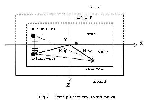
Sound field in the water is determined by considering continuity of both sound pressure and normal particle velocity at the boundary of water, tank wall, and ground , and that free pressure condition as to surface of water, tank wall, and ground . If the later condition is applied to this problem directly, however, the condition: free pressure has to be incorporated in the whole. In this case, it causes increase in time and memory in calculation. On the other hand, it is known that sound field can be solved by using mirror image principles10) . So, this method is applied to solve the present problem. That principle is shown in Fig.2. A dashed line indicates such the state that both water tank and ground were reversed vertically. In this configuration, two sound sources are placed. A source inside the solid line is called as actual sound source and another source inside the dashed line is called as mirror source or virtual sound source. Such two sound sources are 180 degree different in phase but have same amplitude and are placed symmetrically to XY plane. Where Y axis is defined positive to the front perpendicularly. Consequently, if these sounds are superimposed, the field which satisfies surface boundary condition will be obtained. |
||||||||||||||||||||||||||||||||||||||||||||||||
|
|
||||||||||||||||||||||||||||||||||||||||||||||||
|
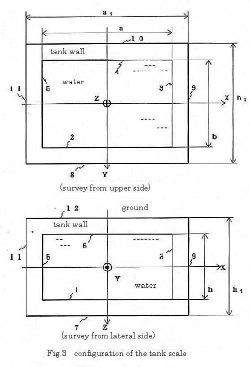
As shown in Fig.3, the boundary between water and tank wall is divided from region 1 to region 6,and the boundary between tank wall and ground is divided from region 7 to region 12. The coordinates of the arbitrary points on region i are defined as(Ri,θi,φi)by polar coordinate system,and as(ri,zi,φi)by cylindrical coordinate system. In the arbitrary point W in the water , the velocity potential Φqgenerated by the spherical wave with volume velocity Qqemanated from point q is given as follows;
where, k is wave number in the water and is expressed by ω/C,(ω:circular frequency,C:sound speed in water),and the time function expressed as exp(jωt) was omitted.
|
||||||||||||||||||||||||||||||||||||||||||||||||
|
|
||||||||||||||||||||||||||||||||||||||||||||||||
|
Moreover, since Eq.(1) satisfies radiation condition ,in the infinite field, it is expressed as power series using polar coordinates variables as follows,
where,jn,hn(2),and Pn are the first kind spherical Bessel function of nth order, the second kind spherical Hankel function of nth order, and the first kind Legendre function of nth order, respectively. R<means min(RW,Rq)and R> mean max(RW,Rq). In Eq.(2), Pn (cosΘqW) is expressed by the additional theorem .re. Legendre function,
Then, in substitution of Eq. (3) into Eq. (2),
where,
On the other hand, at point W , the velocity potential Φr of wave reflected from the tank wall is expressed by power series as follows,
where, Ψnmr(RW)=jn(kRW)Pn|m|(cosθ)exp(jmφ) (5) Anmqis a unknown constant to be determined by the boundary conditions. The velocity potential of wave refracted in the tank wall is defined as ΦT.,, |
|||||||||||||||||||||||||||||||||||||||||||||||||

|
ΦT is also expressed below, by power series,
where, Λnm(RV)=jn(kTRV)Pn|m|(cosθ)exp(jmφ) Υnm(RV)=nn(kTRV)Pn|m|(cosθ)exp(jmφ) (6)
where,nnmeans the second kind spherical Bessel function of nth oder, kTmeans the wave number in the tank wall ,and is given as kT=ω/cT by using cT (sound speed in the tank wall),and ω ( circular frequency). Bnmq,and Cnmqare also unknown constants to be determined by the boundary conditions. The velocity potential of wave which penetrates into ground from the tank wall is defined as ΦD at the point u. ΦD is given as follows, by using power series, since ΦD has to satisfy radiation condition in infinite field.
where, ΨnmD(RU)=hn(2)(kDRU)Pn|m|(cosθ)exp(jmφ) (7)
Dnmqis also unknown constant determined by boundary conditions.
2.2 Determination of unknown constants
Unknown constants Anmq,Bnmq, Cnmq, and Dnmq, are determined by the following boundary conditions. With respect to the normal particle velocity of region i, (where, i=1 ,.., 6) sum total of incident wave and reflected wave is equal to refracted wave which is generated in the tank wall.
-n∇Φq|RW=Si-n∇Φr|RW=Si=-n∇ΦT|RV=Si (8)
where,nis unit vector normal to the surface of region. Siis the vector positioning the surface of region i. n∇is a calculus operator to obtain a differential coefficient with respect to normal direction of the regional surface, and then,
n∇=(nxe1+nye2+nze3)・(e1∂/∂x+e2∂/∂y+e3∂/∂z) (9)
where,nx,ny, and nz are elements of unit vector n as to the direction X, Y, and Z respectively. Incident pressure from water to tank wall is defined as Pq,reflective pressure from tank wall to water is defined as Pr,and refractive pressure into tank wall is defined as PT. Hence, sum total of incident and reflective pressure is equal to refractive pressure,
Pq|RW=Si+Pr|Rw=Si=PT|RV=Si (10)
At region i,(where, i=7,..,12) , on the other hand, since normal particle velocity of scattered wave into ground is equal to that of refracted wave into tank wall,
-n∇ΦT|RV=Si=-n∇ΦD|RD=Si (11)
The pressure of wave refracted from tank wall to ground is defined as PD. Since the pressure of scattered wave into ground is equal to that of refracted wave in the tank wall, PT|RV=Si=PD|RU=Si (12)
Unknown constants ,however, are never obtained strictly , except for such a simple form like a sphere. For this problem, on the other hand, a method obtaining unknown constants by assuming wave mode of structure has been suggested. That is least mean square method, and is called as Mode Matching Method. This is a useful method ,but is difficult to apply for such boundary value problem of the present tank whose surroundings are layered with different mediums, because the values of pressure or particle velocity of each boundary cannot be known. Such problem is often called as sound correlation problem. Here, to determine unknown constants, a new method,Mode Matching Method Expansion ,is proposed.
2.3 Application of mode matching method expansion
In each Eq.(8), Eq.(10), Eq.(11),and Eq.(12), the absolute of value subtracting the right hand side from left hand side , are defined as ε1,ε2, ε3,and ε4 respectively,
ε1=|-n∇Φq|RV=Si -n∇Φr|RW=Si +n∇ΦT|RV=Si | (13) ε2=|Pq|RW=Si+Pr|RW=Si-PT|RV=Si| (14) ε3=|-n∇ΦT|RV=Si+n∇ΦD|RD=Si| (15) ε4=|PT|RV=Si-PD|RU=Si| (16)
where,ε1,ε2,ε3,andε4, should be 0. However,as shown in Fig.3, the boundary shapes with respect to region1, region2… and region12 are not adapted with coordinate system expressed by spherical coordinate. So all these values have errors. Thus, unknown constants Anmq,Bnmq,Cnmq,and Dnmq are determined ,by minimizing the sum of squared errors E ofε1,ε2,ε3and ε4in entire region .These error E are given below,
|
|
E = |
4 |
|
|
|
||
|
Σ |
∫∫ |
εj2ds |
|
|||
|
j=1 |
|
|
|
|||
|
= |
6 |
|
|
|
||
|
Σ |
∫∫ |
|-n∇Φq-n∇Φr+n∇ΦT|2dsi |
|
|||
|
i=1 |
|
|
|
|||
|
6 |
|
|
||||
|
+Σ |
∫∫ |
|jωρΦq+jωρΦr-jωρTΦT|2dsi |
||||
|
i=1 |
|
|
||||
|
12 |
|
|
|
|||
|
+Σ |
∫∫ |
|-n∇ΦT+n∇ΦD|2dsi |
|
|||
|
i=7 |
|
|
|
|||
|
12 |
|
|
||||
|
+Σ |
∫∫ |
|jωρTΦT-jωρDΦD|2dsi (17) |
||||
|
i=7 |
|
|
||||
Here, an subscript of integration is a region. dsi shows the minute element in region i. Furthermore, constant value
;jω represented in Eq.(17) can be removed from integration. And the operation of an absolute value will be
expressed with a complex number.
where, * means complex conjugate. In Eq.(18) to which Eq.(4),Eq.(5),Eq.(6),and Eq.(7)are substituted, the value of E is found not to be related with unknown constants An’m’q*,Bn’m’q*,Cn’m’q*,Dn’m’q*. If partial differentiation ∂E’/∂An’m’q*,∂E’/∂Bn’m’q*=0, ∂E’/∂Cn’m’q*=0 ,and ∂E’/∂Dn’m’q*=0 are applied, then the matrix equation about An’m’q*,Bn’m’q*,Cn‘m’q*,Dn’m’q*is obtained. However, the formulated matrix element representation is omitted on account of screen limitation here. After solving the matrix equation, the value Anmq is obtained. In substitution of this value to Eq. (5), the velocity potential of the scattered wave generated in the tank is obtained. Then, summing this to that of the emanated wave expressed as Eq.(4), vector potential Φr is obtained. Consequently, summing the vector potential generated by a virtual sound source to that, we can obtain velocity potential generated in the tank whose upper boundary faced air. By the vector potential theorem, pressure P is expressed below,
|
where, N means the number of truncation terms of power series.
|
||||||||||||||||||||||||||||||||||||||||||||||||||||||||||||||||||||||||||||||||||||||||||||||||||||||||||||||||||||||||||||||||||||||||||||||||||||||||||||||||||||||||||||||||||||||||||||||||||||||||||||||||||||||||||||||||||||||||||||||||||||||||||||||||||||||||||||||||||||||||||||||||||||||||||||||||||||||||||||||||||||||||||||||||||||||||||||||||||||||||||||||||||||||
|
3. Numerical examples and experimental results
The outside of the tank wall is covered with sand ,and that outside is covered with ordinary soil. However, in calculation, outside of the tank wall were all assumed to be covered with sand. The tank wall is constructed by concrete. The density and sound speed in sand were selected by the references 12), and the density and sound speed in tank wall were selected by the references 13), 14). Parameters for calculation are shown in Table.1. In Table.1, the scale of tank is equal to that of piled tanks vertically.
|
|||||||||||||||||||||||||||||||||||||||||||||||||||||||||||
|
|||||||||||||||||||||||||||||||||||||||||||||||||||||||||||
|
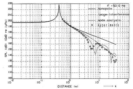
In Fig.4,the sound pressure generated at Y=0 ,Z=2.63m ,in the direction paralleled to X axis is shown. That direction is on the line of the cylinder axis of the sound source ,so is called as “sound axis”. For comparison, four kind of data are shown in Fig.4.'monopole' is the sound pressure of infinite free field (see Fig.1), 'image interference' is the sound pressure of semi-infinite water field whose upper side is air ,'mode analysis' is sound pressure in the tank where both reflection and transparency are considered. And 'experiment' is the experimental result. From Fig.4, 'monopole', 'image interference', and 'mode analysis' show the almost same results within 1dB in the range of 1m . On the other hand, in the range beyond 1m, both 'image interference' and 'Mode analyses' that are affected by the water surface reflection become lower than 'monopole'. In addition, 'mode analysis' is extremely lower than 'monopole' or 'image interference' in the far field about 7m or 25m. In comparison 'experiments' with 'mode analysis', they are almost alike within the distance of 3m. Beyond 3m, the distance where sound pressure becomes minimum is nearly 7m or 25m in 'mode analysis' ,while nearly 5.5m or 30m in 'experiments'. The reason of this discrepancy is as follows; 1) In calculation, a wave function without considering the internal loss factor 15), in the sandy region. 2) As actual water tank is constructed by the concrete material in which some steel ribs are inserted, and the wall thickness of water tank is not constant. 3) The parameter values re concrete or ground used in calculation differ from actual data.
|
|||||||||||||||||||||||||||||||||||||||||||||||||||||||||||
|
Fig4 sound pressure generated at X (Y=0,Z=2.63m) |
|||||||||||||||||||||||||||||||||||||||||||||||||||||||||||
|
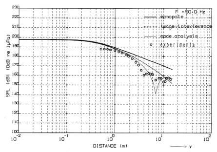
From these results, sound pressure downed in the distance near both 7m and 25m seems caused by the reflection from wall of the water tank. The sound pressure generated in the direction Y (X=0,Z=2.63m) is shown in Fig.5. In this figure, 'image interference','mode analysis', and 'experiments' are found to be lower than 'monopole' . In the range, Y>1m and Y<3m, the 'experiments' is almost alike the 'mode analysis'. However, inside the distance of 1m,'experiments' indicate lower than 'mode analysis', for example, 5dB lower in the distance of 0.6m.This difference seems caused by reflection loss of air inside the cylindrical enclosure of sound source. Hence, it was concluded that sound pressure obtained by the experiments was almost same to that of 'monopole', within 1m re sound axis. To the contrary, outside 1m in both sound axis direction and the direction perpendicular to the acoustic axis, such sound pressure representative to the 'monopole' was not obtained owing to reflection from both water surface and water tank wall.
|
|||||||||||||||||||||||||||||||||||||||||||||||||||||||||||
|
Fig.5 sound pressure generated in the direction Y (X=0,Z=2.63m) |
|||||||||||||||||||||||||||||||||||||||||||||||||||||||||||
|
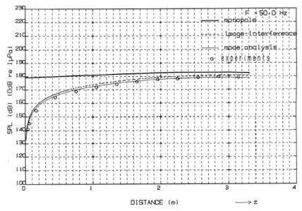
The sound pressure generated in the direction Z (X=2.3m,Z=0) is shown in Fig.6. 'experiments' is lower than 'monopole'. 'experiments' is close to 'monopole' at the deep position in the tank. This is the reason that water surface reflection scarcely affects to 'monopole' at the deep position. However, other sound pressures except for 'monopole' are 2dB lower than 'monopole'. So , in such water tank as depth is 3.2m , the water surface reflection seems affective to 'monopole'. |
|||||||||||||||||||||||||||||||||||||||||||||||||||||||||||
|
Fig.6 sound pressure generated in the direction Z (X=2.3m,Z=0)
|
|||||||||||||||||||||||||||||||||||||||||||||||||||||||||||
|
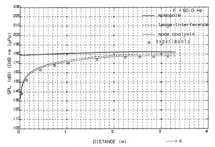
The value of the generating sound pressure of the Z-axis direction containing X= 0 and Y= 2.3m is shown in Fig. 7. 'experiments' is lower than 'monopole'. Moreover, 'mode analysis' , 'image interference' ,and 'experiments' are almost same. From these results, the free field sound pressure is found to be equal with experimental data ,at less than 1.5m along Z-axis directions of the tank. However, the region within 1m in which sound pressure is not in inverse proportion to the distance is near field . Thus, sound pressure in the far field cannot be converted from this measured value. On the other hand, as for 'mode analysis' proposed here, the sound field considering reflection of surface and tank wall can be calculated. Then in the further distance than 5m,'mode analysis' was found mostly suited to the experimental results. So, this proposed technique seems useful to the sound field prediction within the echoic tank. |
|||||||||||||||||||||||||||||||||||||||||||||||||||||||||||
|
Fig.7 sound pressure generated in the direction Z (X=0,Y=2.3m)
|
|||||||||||||||||||||||||||||||||||||||||||||||||||||||||||
|
4.Conclusions In a water tank surrounded by the infinite ground, a sound field generated by the two-point sources as a model of low frequency sound source of cylindrical type of which ends have discs was calculated by the Mode Matching Method Expansions, and was compared to the experimental results. Moreover, free field sound pressure generated by monopole source, and semi free field sound pressure generated by method of 'image-interference' were calculated .and were compared to the experimental results. As conclusion, the error between experimental results and mode analysis results was found large near the sound source enclosure surface about a direction perpendicular to the sound source axis. This is considered to be the influence of reflection of the air inside the enclosure. Taking the enclosure shape into consideration in calculation will be tried to prove this discrepancy in the future.
|
|||||||||||||||||||||||||||||||||||||||||||||||||||||||||||
|
References 1)R.Woodcock and J.Nicolas, “A generalized model for predicting the sound transmission properties of generally orthotropic plates with arbitrary boundary conditions,” J.Acoust.Soc.Am.97(2),p1099-1112,(1995) 2)K.m.Liew.C.W.Lim.”Vibratory Characteristic trapezoids,” J.Sound Vib.183(4),p615-642,(1995) 3)P.A.A.Laura an R.Gutierrez,”Fundamental frequency of vibration of clamped plates of arbitrary shape subjected to a hydro-static state of in-plane stresses,” 4) M.Okajima, C.B.Burroughs, and J.P.Charpie,”An analytic model for the frequencies of resonance of rectangular plates of variable curvature and thickness,” J.Acoust .Soc.Am.97(2),p1053-1060.(1995) 5)H.Ikuno and K.Yasuura,”numerical calculation of scattered field from a periodic deformed cylinder using the smoothing process on the mode matching method,”Radio Sci.13.p937-946,(1978) 6) W.Williams.et al.,”Acoustic radiation from a finite cylinder,”J.acoust.Soc.Am.36 (12), 2316-2322, (1964) 7)H.Suzuki,J.Tichy,”Diffraction of sound by a convex or concave dome in an infinite baffle,” .Acoust.Soc.Am.70(5).p1480-1487,(1981) 8)D.T.Diperna and T.K.Stanton,”Sound scattering by cylinders of non-circular cross section: A conformal mapping approach,” J.acoust.Soc.Am.96.p3064-3079,(1994) 9)Hayasaka Toshio and Yoshikawa shokichiro,”Onkyo Shindoron”Maruzen CO.,Ltd.Tokyo,1974,P642,645 10)reference9),p569-570 11)Moriguchi Shigekazu,et al,”SugakukoshikiⅢ,Tokusyu Kansu”,Iwanami Syoten Co.,Ltd..,Tokyo,1977,P218,220 12)Motooka seiichi and Okujima Motoyoshi,”Electromagnetic Induction Type Sound Source Used for Detection of Bodies Buried in Underground”,J.Acoust.Soc..JapanVol.29 ,No.7,p403-409,(1973) 13)The National Astronomical observatory of Japan edit,”Science chronology”,Maruzen Co.,Ltd.,Tokyo,(1995) 14)Nishimaki Masao,”Denkionkyo shindo gaku”,Koronasya Co.,Ltd.,Tokyo,p47,(1978) 15) Motooka seiichi and Okujima Motoyoshi,”Measurement of Frequency Characteristics of Attenuation Constant in Sand by Impulsive Sound Wave”, J.Acoust.Soc.JapanVol.30, No.6, p325-328, (1974)
|
|||||||||||||||||||||||||||||||||||||||||||||||||||||||||||
|
|
|
|
|||||||||||||||||||||||||||||||||||||||||||||||||||||||||